 FloKra
2fa26e7d15
documentation update, schematic/layout as image
FloKra
2fa26e7d15
documentation update, schematic/layout as image
|
5 лет назад | |
|---|---|---|
| .. | ||
| FloKra_Modules.pretty | 5 лет назад | |
| Board.png | 5 лет назад | |
| ImpCounter-cache.lib | 5 лет назад | |
| ImpCounter.kicad_pcb | 5 лет назад | |
| ImpCounter.pro | 5 лет назад | |
| ImpCounter.sch | 5 лет назад | |
| Modules-FloKra.bck | 5 лет назад | |
| Modules-FloKra.dcm | 5 лет назад | |
| Modules-FloKra.lib | 5 лет назад | |
| README.md | 5 лет назад | |
| Schematic.png | 5 лет назад | |
| fp-info-cache | 5 лет назад | |
| fp-lib-table | 5 лет назад | |
README.md
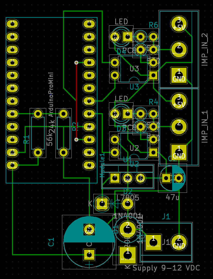
DualS0ImpCounter - Hardware
Arduino based hardware for capturing impulses from S0 impulse meters.
Hardware
- based on Arduino Pro Mini (or clone, with ATmega 328p MCU)
- power supply using a 12VDC wall plug
- big buffer capacitor only for the MCU itself, right before it´s diode decoupled 5VDC regulator,
- resistor network from 12VDC supply to ADC input to detect power loss early enough
- 2 S0 impulse inputs using optocouplers, active LOW (compatible with S0 outputs, which are usually open collector outputs)
- connection to host over RS232, so NOT USING USB POWER SUPPLY
- RS232 connection without DTS signal, so that the MCU cannot be surprise-reset by the host on (re-)connect
- reset circuit (connection from a GPIO out to /RES input)
Schematic

Board Layout